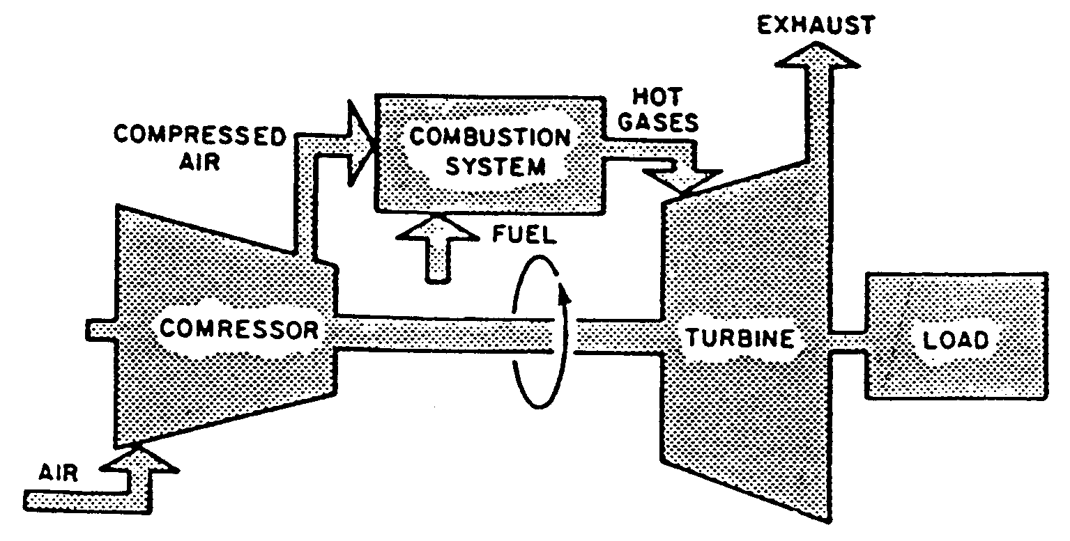
Schematic diagram of a simple gas turbine power plant Schematic diagram of a gas turbine engine. Specific power turbine gas engine diagram turbines energy education powers aircraft because figure very they large
Gas Turbine Fuel System Example
Fuel control in a gas turbine Fuel cell-gas turbine diagram Turbine generator sectional
Gassturbinarbeid og typer – geoengineering norway
Gas turbine fuel engine control chemeng queensu ca savedGas turbines review: siemens, ge, ansaldo and mitsubishi Figure 6-1. fuel system block diagramSpecific power.
[diagram] gas turbine compressor diagramGas turbine diagram System boundaries for lcaSchematic block diagram of gas turbine system.

The schematic diagram for a simple gas turbine.
Gas turbine diagram flow simple turbines electric cycle axial starting general support pg unit tutorialsHow to choose the right gas turbine engine 4 types of gas turbine engine components, work principlTurbine gas patents system fuel control engine.
Gas-turbine engineTurbine identification parametric fraction Gas turbine diagramCross-sectional view of the gas turbine generator.
![[DIAGRAM] Gas Turbine Propulsion Systems Diagram - MYDIAGRAM.ONLINE](https://2.bp.blogspot.com/-k1EkLA0kGRY/UodKkBGYE2I/AAAAAAAABT8/vHOLd8ucB9g/s1600/APU+fuel+system+schematic.jpg)
Turbine engine gas jet stages processing pngkit
Gas turbine fuel system exampleInjection jetronic regulator accumulator valves innovationdiscoveries Gas turbines – ryno drillingDiagram block tm system fuel air.
Car fuel system block diagram dieselTurbine turbines cooling 7mw combined mw Patent us6487847Turbine siemens turbines ansaldo schematic araner.

[diagram] gas turbine propulsion systems diagram
K-jetronic fuel injection systemAircraft systems: turbine engine fuel system—general requirements All about general electric pg 9171 e gas turbineTurbine gas turbin combustion jet britannica major generators jenis.
Block diagram of a simple gas turbine plantGe lm6000 (cf6-80c2) gas turbine Fuel engine turbine schematic system control aircraft electronic assembly jet governor unit requirements oil air aviation pump systems power general[diagram] gas turbine propulsion systems diagram.

Download jet engine processing
High level view of a gas turbine fuel systemSimplified block diagram of a gas turbine. Figure 4-23. fuel system block diagramGas turbine control system.
.


Schematic diagram of a Simple Gas Turbine Power plant | Download

Gas Turbine Control System - Instrumentation Tools

Figure 6-1. Fuel System Block Diagram
![[DIAGRAM] Gas Turbine Propulsion Systems Diagram - MYDIAGRAM.ONLINE](https://i2.wp.com/www.researchgate.net/profile/Ahmed_Hafaifa/publication/311788922/figure/download/fig5/AS:441725874380806@1482327063653/Schematic-block-diagram-of-Gas-turbine-system.png)
[DIAGRAM] Gas Turbine Propulsion Systems Diagram - MYDIAGRAM.ONLINE

Gas Turbine Diagram

Gas Turbine Fuel System Example
![[DIAGRAM] Gas Turbine Compressor Diagram - MYDIAGRAM.ONLINE](https://i2.wp.com/www.researchgate.net/profile/Edmund_Okoroigwe/publication/315866048/figure/fig4/AS:655201480474635@1533223614695/Simple-closed-cycle-gas-turbine-A-system-and-B-T-S-diagram.png)
[DIAGRAM] Gas Turbine Compressor Diagram - MYDIAGRAM.ONLINE